di/dt related EMI issues on Power supply
- Francesco Poderico

- Apr 30, 2024
- 3 min read
In terms of EMI, it is very difficult to have a product that is both efficient and low noise.
Today I'd like to discuss some typical issues you may encounter when designing an efficient power supply.
As you can see, I have not used the word DC/DC converter, but power supply, since this issue may also occur in linear power supplies.
Issues due to fast recovering diodes
Fast recovering diodes are used in our power supply designs to maximize efficiency. Whether we are designing a DCDC converter or a linear power supply, it doesn't matter. Good electronic engineers always try to make their designs as efficient as possible, which is why they often use fast recovery diodes.
Fast-recovering diodes can help reduce the temperature (the more efficient the diode, the less wormer it is), but will also pose some challenges in terms of EMI emissions.
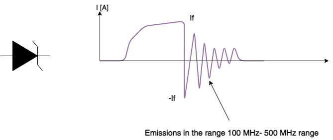
As a result, some precautions need to be taken, otherwise, we may experience emission issues between 100 MHz and 500 MHz.
Let's look at the physics behind that, as well as the reason for the emission in the range of 100 MHz to 500 MHz.
What is a fast recovering diode?
A fast-recovering diode, as the name implies, is a device that can switch very fast, so the transition between "ON -> OFF" and "OFF -> ON" is very fast.
Imagine the diode is conducting a large current and then suddenly the voltage across the diode is inverted (from conduction to nonconduction). There will be a high current (same magnitude as the forward current) for a short period of time.
In the case of a diode that conducts 100A, and the voltage suddenly reverses, we will have -100A in the opposite direction, It last only a few nseconds. We will see that this current can cause some EMI problems, as well as faults in some cases (see later).
Why do we have this issue?
The reason for this is that any PN diode has a junction capacitor which can be as high as tens of pF to a few nF (yes nF). Imagine a 100pF parallel to an ideal diode, and you reverse its polarity instantly, what happens to the If current? The answer is simple, the If will become -If and eventually decay.
This information is called (junction capacitor) Ct in the datasheet, and usually is given for a specific reversed voltage.
Usually the higher is the switching voltage, the lower is the is the capacitance

Example of ringing due to a fast recovering diode.
The impact of ESL on the ringing
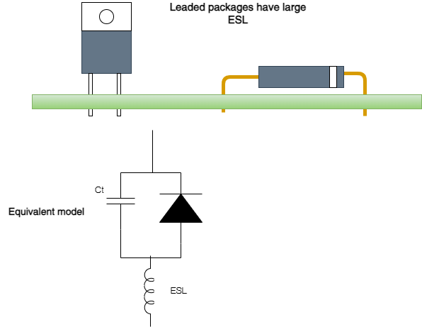
The package of your diode has a huge impact on the ESL (Equivalent Series Inductor). Most diodes designed for large currents are in TO-220, TO-247, or similar packages, and therefore have a large ESL. It's not included in the datasheet, but it should be included in the spice model, so you can simulate it if you have a good spice model.

The equivalent ESL of a diode with leads is shown in the above drawing.
How do we solve the ringing and improve EMI?
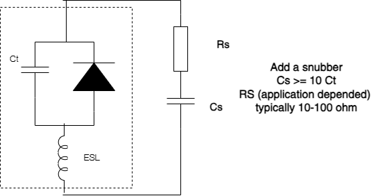
The simplest way is to add an RC snubber in parallel to the diode.
The capacitor Cs needs to be selected to be at least 10 times higher the the Ct provided in the datasheet, for exampke if Ct is 100 pF, then Cs = 1nF (or higher).
The resistor shoud be the higher as possible, this is application dependent, therefore I will leave the selection of Rs up to you.

Example of RC snubber.
You will see RCs in parallel with diodes (sometimes resistors parallel with inductors) in schematics. You know why.
In this post, I hope I was able to convey something from my design experience that will aid you in designing efficient power supplies.


hi Mr Francisco, I believe that SIC schottky diode is the excellent choice for power supply secondary side rectification, it has almost zero reverse recovery time, very low junction capacitance, low forward voltage drop, ultra fast switching and it can conduct large amount of current which makes it an excellent choice, the only issue is that it's quite expensive as you compare it with discrete fast schottky diodes