In a previous article, I discussed the common mode coupling on the PoE (Power Over Ethernet) DCDC converter that I discussed a few months back. It is a similar mechanism that happens when we design our own AC/DC converters. Based on some of the comments that I have received, it seems clear that for some people, the mechanism for coupling the common mode current was not clear to them as to how it worked. In this article, I would like to try to clarify a few points.
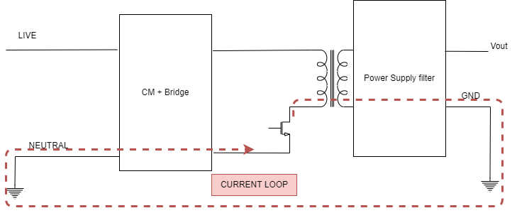
Let's look at the following diagram.

Our AC/DC converter has a primary side referred to as the "HOT side" that is either directly or indirectly connected to the Live and Neutral of our main, while the MOS source is usually connected to the Neutral.
When the MOS is switching, since we usually have a high voltage at the primary of the MOS, the dV/dt resulting from switching the input voltage. This high dV/dt causes some current to be coupled "via" the winding capacitor between the primary and the secondary side of the transformer, (because of the high dV/dt indeed). This can be seen in the diagram below.
Let's assume that the GND of the equipment is connected to the Earth, which is very common in many applications. We have created a common mode current that starts from the switching MOS and goes to the winding capacitor from the primary to the secondary, then to the PCB GND, then to the earth, and then back to the Neutral.
As mentioned earlier, this is one of the two main mechanisms that cause common mode emissions due to AC/DC converters (the second mechanism I will explain in a different post).
Now, I believe it should be clear to you how the common mode current has been created and what the loop is.
This current loop creates EMC issues, and the chances that you are most likely to fail conductive emissions are quite high.
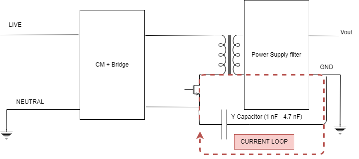
The easy way to fix this problem is to use a safety-approved capacitor (Y type) in place of the original capacitor. The typical value fo of capacitor of this type is between 1 nF and 4.7 nF. Keep in mind that the higher the value of this capacitor, the higher will be the leakage current that will be generated as a result (I discussed this earlier in this post). Due to this reason, another way to reduce this is to reduce dV/dT by a certain amount. Unfortunately, this causes heating issues, and in some cases, it is not possible to correct the problem. As another option, we can "shield" the transformer in order to prevent damage to it. However, this method may result in other problems that I won't discuss in this post.
Hopefully, you have enjoyed it, and I hope that you have a better understanding of how to avoid this type of problem in the future.
Comments