Cable length strategy during radiated emissions.
- Francesco Poderico
- Dec 4, 2022
- 4 min read
Radiated emissions from a product don't always turn out the way we want. And having a plan for troubleshooting emissions when they exceed or are near the limits is a smart idea.
If you follow me on my blog, you should know by now that I often share design tips that aren't widely known or not widely understood by the design community in general. There is a troubleshooting technique that can be used when you have broadband noise that I would like to discuss today. For example, coming from a DC/DC converter or an AC/DC converter and using the cables connected to your unit to be able to emit higher frequencies than 30 MHz, for example.
What are we going to learn?
Our goal is to learn that when we have broadband noise in our measurement, by changing the length of the cable of our EUT (Equipment Under Test), we can change the envelope of our emission. We can "increase" or "decrease" the peak of the emission(s) by simply increasing or decreasing the length of cables used during the test.
Please note, you should only use this technique when troubleshooting your design. Definitely not as a solution!
This is something I use to check quickly if broadband noise can be associated with this or that part of the circuit, and filters (ferrite, inductors, etc.) on cables don't give me enough attenuation to understand the issue.
When I test a product, I usually go to a testing lab with three sets of cables, at the very least.
For example, the first set is 2.5 meters long.
I made a set of cables as short as I could.
An extended set of cables longer than 5 meters.
I started the radiated emission using a cable set of 2.5 meters.
For example, let's say we had an emission above the limits, and the emission graph shows broadband noise between 100 MHz and 300 MHz.
Whenever the emission is a broadband emission in the above range, in my experience, it is most lucky that the noise source is a DCDC or an AC/DC converter. The common mode noise source generated by the switching MOS uses cables as antennas as part of its radiation and we see the result in the radiation emission graph.
Occasionally, ferrites won't work because the emissions are too low, they aren't practical, or they don't work at all.
We need to understand why cables behave like antennas. As a result, we will be able to change the radiation efficiency of our cables and move their radiation emissivity up and down the frequency spectrum.
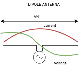
Take a look at the following drawing:

Dipole antenna
Dipole antennas are the simplest antennas.
The maximum efficiency of a dipole antenna is at wavelength λ/4.
At lower frequencies, it behaves as a capacitor, while at higher frequencies, it acts as an inductor. While at resonance frequency it behaves like a resistor (between 75 and 50 ohms ish)
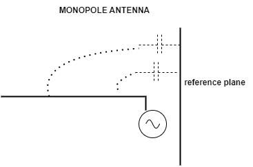
An antenna can also be created by using a reference plane in place of one of the two wires. An antenna like this is called a monopole antenna. Similar to a dipole antenna, it has pretty much the same characteristics.

typical monopole antenna
So a monopole antenna works exactly like a dipole antenna. It is formed by 2 elements, the wire and the reference plane.
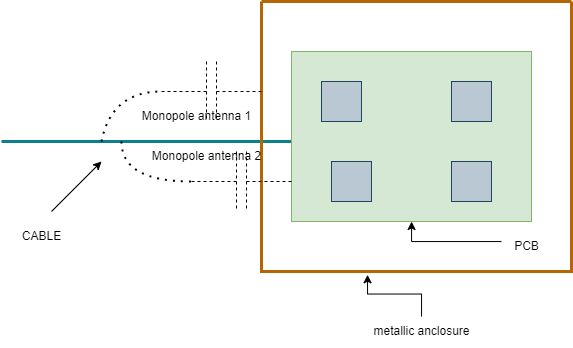
Now, have a look at a typical EMC setup where we have a cable connected to our EUT (Equipment Under Test).
In our case the wire can be any of our cables.
The reference plane can be either the PCB's reference plane or the EUT's metallic enclosure.
Now since we know that the monopole antenna resonates at λ/4, we can use this information to shift "up and down" in the spectrum range the emission peak of a broadband noise, like for example the emission of a DCDC converter.
For example, let's imagine we have some broadband emissions above the limits around 200 MHz (using the first set of cables, e.g. 2.5 meters).
We can repeat the scan using shorter cables (our second set).
Have we solved the emissions problem? YES! -> use longer cables now! Do we have "moved" the emission peak at 30 - 50 MHz ? YES! -> the cables are behaving like a monopole antenna! Let's fix it!
Now the question is, "Francesco why don't you just add some ferrites?"
The fact is, sometimes it is just not possible. It may be ineffective, or the size of the ferrites is not a practical solution.
It is better to "break" the antenna, by damaging it's structure.
There are several ways to accomplish this. The first step is to identify the reference plane. Is it PCB GND? Or is it a metallic enclosure?

Once we have identified this, what we need to do is connect in AC (or DC sometimes) the reference plane to the cable. e.g. using a capacitor, or an inductor or a mix of the two. Most of the time the value of the capacitor is irrelevant, what we need to do is just "break" the antenna made by the cable wire and the reference plane.
I hope you enjoyed this post, and I hope next time, rather than start adding ferrites everywhere, you stop for a second and try to understand.... "where is my antenna?" and "How I can break it?"
Comments