A PDN design note (bypass capacitors)
- Francesco Poderico
- Jan 9, 2023
- 2 min read
PDN design is not an easy task, and it can be challenging.
One of the most common mistakes is to follow so-called "rules of thumb" that work 90% of the time, but not 100%, so it is your responsibility to determine when these rules are valid or not.
Adding a 100 nF capacitor to each power pin in parallel with a 10 nF capacitor is one so-called rule of thumb. In order to improve the impedance of our power plane at frequencies above its resonance frequency, we use a 10 nF capacitor. Do you believe this to be true?
LTSpice can help us do some analysis!
The Wurth website offers a library called WCAP-CSGP that you can download if you wish to repeat this simulation.
Wurth offers excellent tools, such as libraries for most CAD and simulators like LTSpice.
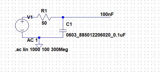
Let's simulate the following circuit:

FIG. 1 C1 is a 100 nF capacitor, R1 simulate the 50 ohm of a signal generator
A signal generator's output impedance is 50 ohm in R1, simulating its output impedance. The C1 is a 0603 100nF.
Figure 2 shows that this capacitor has a resonance frequency of 23.5 MHz. Above fr1, the capacitor acts like an inductor, but below fr1 it acts like a capacitor.

FIG. 2 impedance of C1 over the frequency
The same test can now be repeated with a 10nF capacitor.
Compared to the 100 nF capacitor, the 10 nF capacitor has a lower impedance for frequencies above 62 MHz. Its resonance frequency is fr2 = 98 MHz.

FIG. 3 100 nF in blue, 10 nF in green
So, it would seem logical to assume we would get a better impedance at all frequencies if we put the 2 capacitors in parallel. However, this is far from the truth.

FIG4. 10 nF in blue, 100 nF in green, 10nF//100nF in red
Figure 4 shows that when we parallel the 10 nF capacitor to the 100 nF cap
acitor, there is a frequency range (in our case, between 51 MHz and 73 MHz) where the parallel impedance is higher.
We have created a parallel resonance circuit by connecting fr1 and fr2, where the 100 nF capacitor acts as an inductor and the 10 nF acts as a capacitor. As a result, we have created a tank circuit with a parasitic inductor of (approx.) 1.5 nH in parallel with a capacitor of 10 nF.
Does this pose a problem?
If you have a 20 MHz clock in your design, then the third harmonic may well fall within this range. As a result, in my PDN budget, when I select the bypass capacitor, I perform this analysis to make sure any clock (or any third order harmonic) will not be within the "parallel" resonance frequency.
It is possible to conduct this type of analysis using PDN tools. As an "old school engineer," I still prefer to have full control over my design, and I still perform this type of analysis by hand.
I haven't considered the self-resonance frequency of the plane. I may write about this in another post.
I look forward to seeing you next time.
Comentários